PHYS2020-Arduino-Quick-Start
ANU PHYS2020 Thermodynamics Course Arduino Quick Start Guide
Tony.Yan @anu.edu.au


- This is a guide for setting up an Arduino for data logging.
- You can download all the source code from releases
- The sample code performs basic data logging of various kit components. We encourage you to extend and customise it to your project-specific needs.
- Make sure to double-check any pin connections before powering on, even though Arduino has some built-in protections, it’s still possible to fry something…
- Begin by completing the Connecting to Arduino, followed by the section about your specific sensors. Then you could proceed to Recording Data to SD Card.
- Note: some sections from this guide are TLDR versions of various online guides, with some pin changes to integrate the SD card module. You’re encouraged to develop your own codebase.
- For reference: I’m using macOS 15.6.1, Apple Silicon, Arduino IDE 2.3.6, Arduino Nano and various electronics modules from Adrian.
Table of Contents
- ANU PHYS2020 Thermodynamics Course Arduino Quick Start Guide
Connecting to Arduino
First, download Arduino IDE (integrated development environment) from https://www.arduino.cc/en/software.
Once you have the Arduino IDE installed, we need to verify that the Arduino works by connecting it to your computer and the IDE.
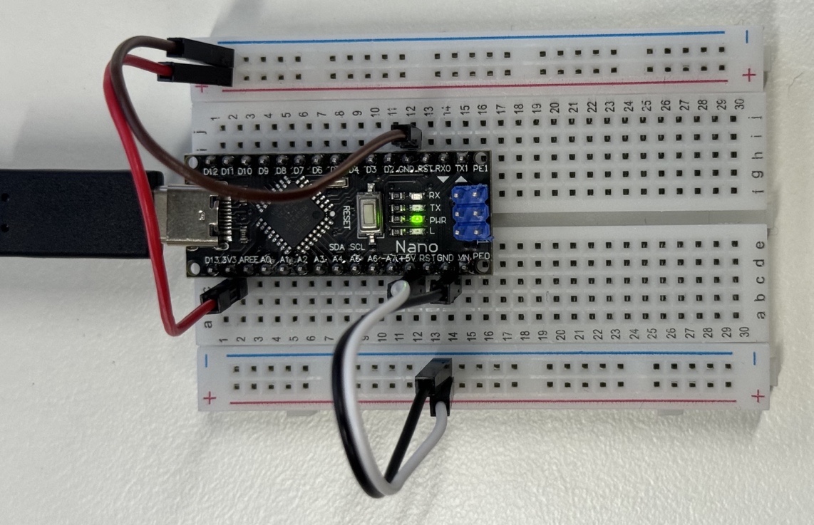
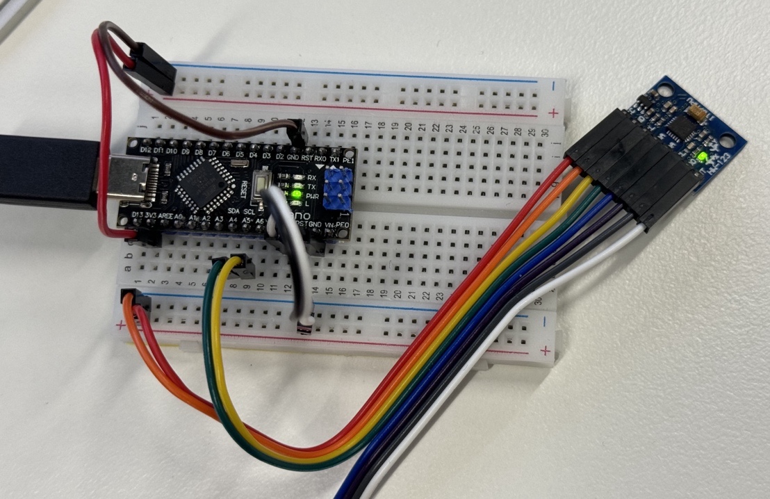
As illustrated in the figure below, I also strongly recommend mounting your Arduino Nano onto a breadboard and connecting the 5V and 3.3V to each power rail on the breadboard. This makes connecting various modules much simpler later.
As a side note, breadboards internally are connected like follows,
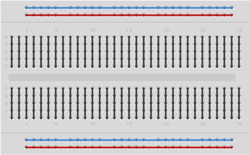 So you can have 3.3V power rails on the top and another 5V rails on the bottom.
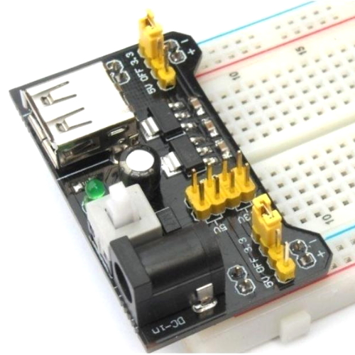
Note, these 5V and 3.3V are regulated by Arduino internal components, you can use them to power a few chips. But when powering lots of modules or a display, I suggest using the breadboard power supply (picture below and Adrian should have some on requests). If you decide to use one of these, make sure you set the jumper pins correctly and test with a multimeter, i.e. don’t connect the 5V power supply to the 3.3V pin on Arduino, you may fry it.
So you can have 3.3V power rails on the top and another 5V rails on the bottom.
Note, these 5V and 3.3V are regulated by Arduino internal components, you can use them to power a few chips. But when powering lots of modules or a display, I suggest using the breadboard power supply (picture below and Adrian should have some on requests). If you decide to use one of these, make sure you set the jumper pins correctly and test with a multimeter, i.e. don’t connect the 5V power supply to the 3.3V pin on Arduino, you may fry it.
Our Arduino Nano uses a USB Type-C connector; you can connect it to your computer with any Type-C cable and Arduino can be powered from Type-C.
The Arduino IDE will preload a default BareMinimum script (Menu -> File -> Examples -> Basic -> BareMinimum) so you can test your connections to your Arduino.
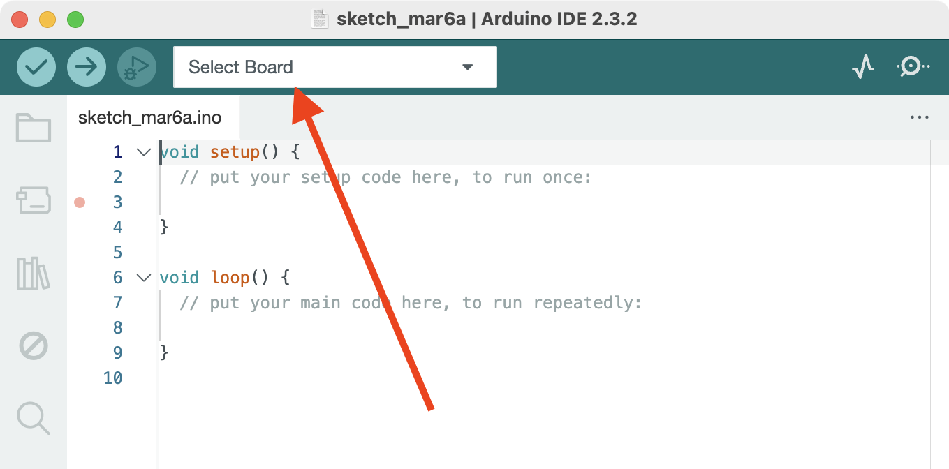
Configure the IDE to our specific Arduino by clicking Select Board
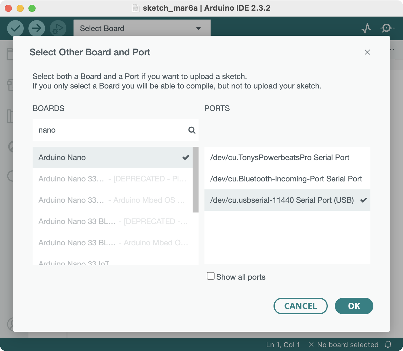
Select Arduino Nano and its USB Serial Port.
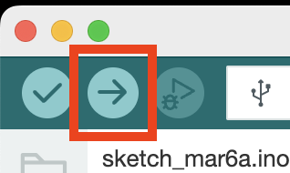
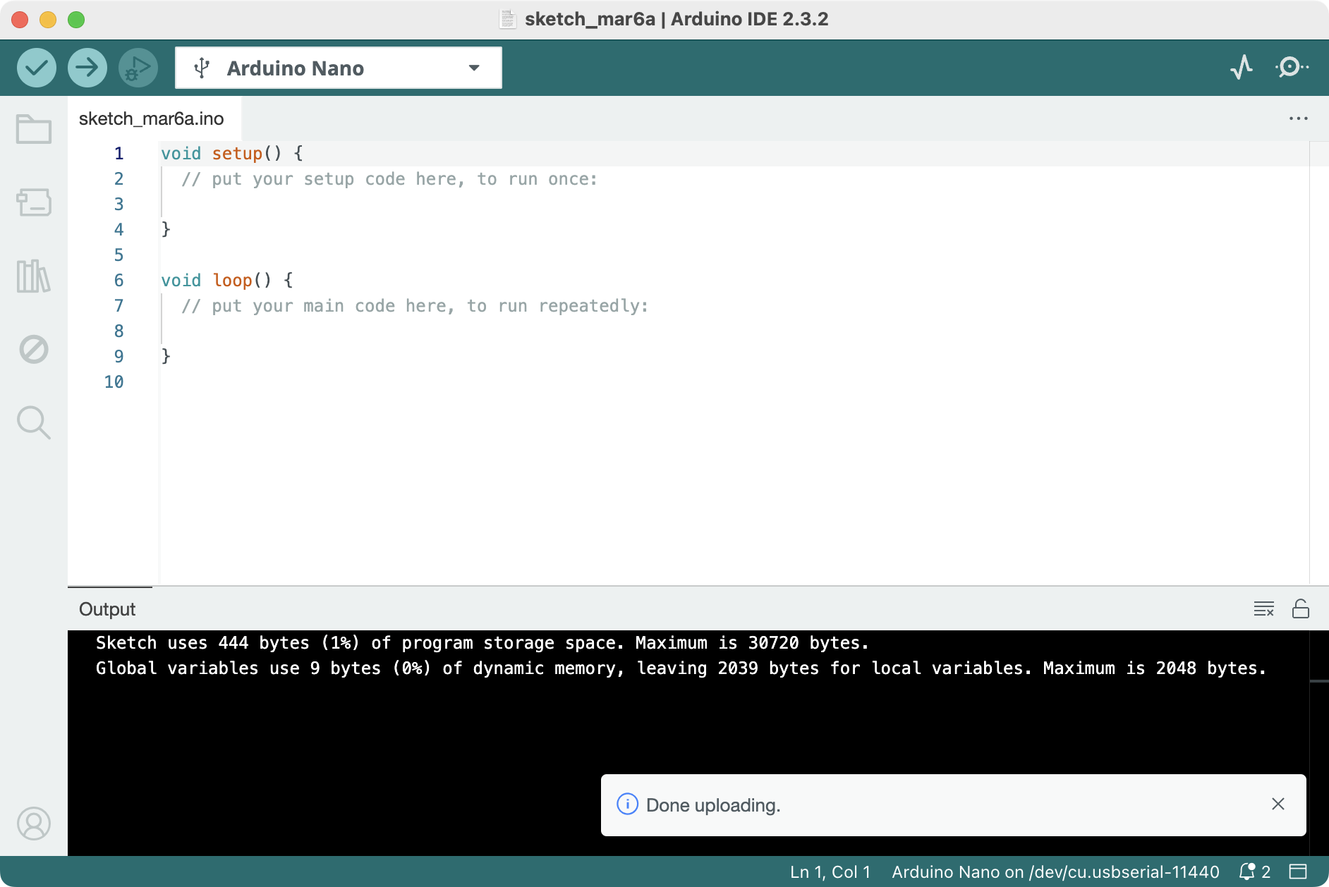
Then, you can try uploading the BareMinimum script onto your Arduino by pressing the Upload icon (or Menu -> Sketch -> Upload or Cmd-U).
You might experience the following error saying the programmer is not in sync
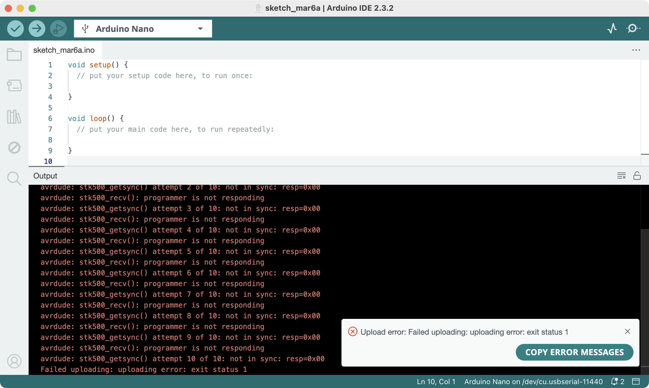
In that case, you need to go to Menu -> Tools -> Processor and select: ATmega328P (Old Bootloader)
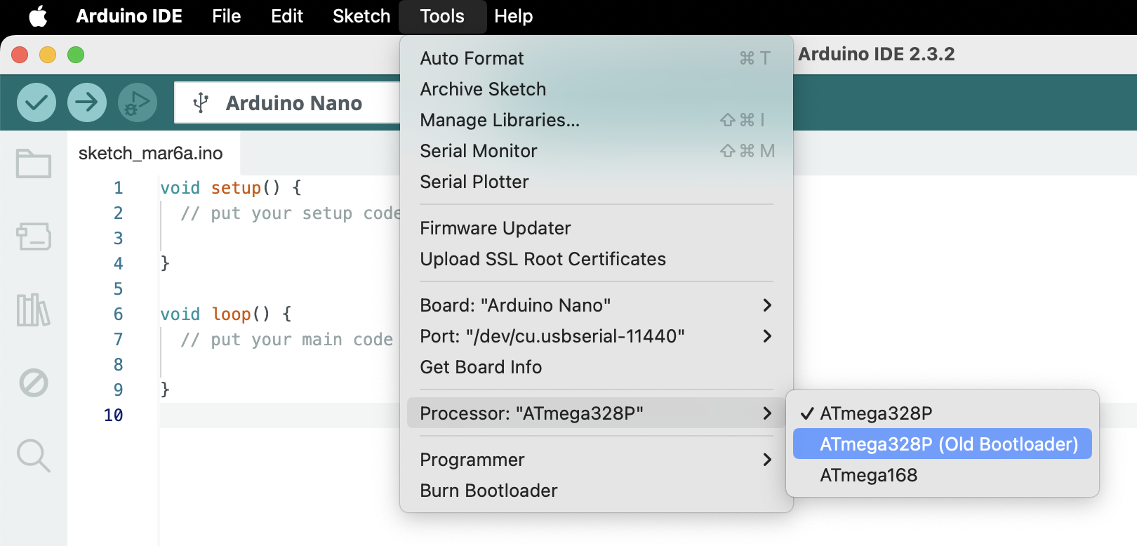
Then try upload again and it should upload without error.
Other Common Issues/Troubleshooting:
- Disconnect all the pins except the USB cable.
- Press the reset button on the Arduino before uploading.
- Try running the Arduino IDE in administrator/sudo mode.
- Close other apps that might be using the COM port.
- Restart computer.
- Check if COM/Serial port appears in Device Manager (Windows) or System Information (macOS).
- Reinstall the latest driver (CH340, FTDI).
- Check if the Arduino is detected in the IDE (
Tools -> Port). - Check the correct Arduino board is selected in the IDE (
Tools -> Board). - Try different USB cable.
- Try different USB ports, avoid using adapters.
- Try different Arduino.
- Email us 😉👍.
General Info and Tips about using Arduino in PHYS2020 Project
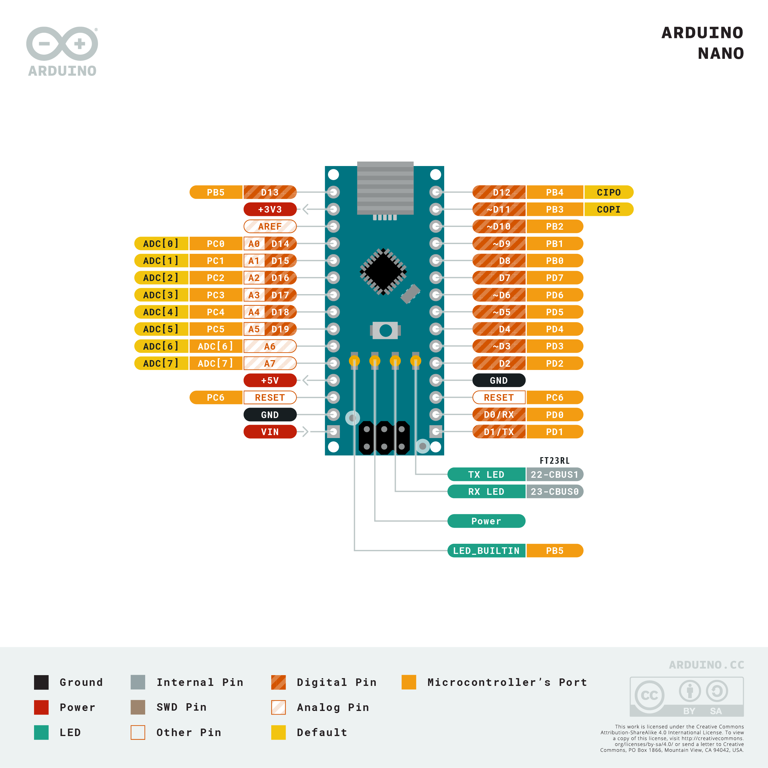
You might find the following Arduino Pin layout helpful (available here).
- If you want to power the Arduino without connecting it to a computer, you can use either
- 6-20V unregulated external power supply (pin 30 VIN), e.g. a 9V battery.
- 5V regulated external power supply (pin 27 +5V). e.g. provided breadboard power supply, you might prefer this if you want to use some high current modules such as a display.
- The power source is automatically selected as the highest voltage source.
- In general, disconnect all unused components from the Arduino pin. Some Arduino libraries will hardcode specific pins and send current through without warning.
- Be careful about which voltage rail you connect the modules to! Some modules come with a built-in voltage regulator, so you can connect them to either 3.3V or 5V, while some don’t and have to be connected to 3.3V; otherwise, they could get permanently damaged.
- You should probably test each of your sensors and make sure they meet the manufacturer’s claims before quoting their measurements scientifically, e.g., knowing their precision, measurement range, systematic error, and response time.
- AI & LLM are fantastic at generating Arduino code and general Q&A, just make sure you understand every line it generates before uploading to Arduino, especially the physical pin connections match the code. Hint: GitHub Copilot offers many most advanced AI models for free to education accounts.
- I strongly recommend some kind of version control of your code and you can include the version histories as part of your final submission. I mostly use Git hosted on GitHub, there are also GitLab and ANU self-hosted GitLab (though I will not recommend the last one, it consistently crashes around the end of each semester).
- Arduino Official Documentation and Arduino Official Forum are also good sources to look up for any issues.
- https://lastminuteengineers.com/electronics/arduino-projects/ provides extensive and detailed guides on Arduino modules. I strongly recommend reading them to understand the module you are using, especially if you want to go beyond the sample codes. (I’ve also stolen some figures from their website for educational purposes.)
MAX6675 Temperature Sensor
This is mainly used in the 2024 course, and you should be using MAX31855 instead.
For a more detailed guide on using the MAX6675 module, please read https://lastminuteengineers.com/max6675-thermocouple-arduino-tutorial/
The kit includes
- Type-K thermocouple probe
- M6 threads
- measurement range 0-80ºC. TBC!
- MAX6675 breakout board,
- 12-bit ADC (analog to digital converter),
- temperature range 0-1024ºC with resolution of 0.25ºC (12-bit)
- accuracy ±3ºC (however, in my experience, I got ±10ºC errors, so please check your probe is not faulty).
The following table shows the connections used in the sample code:

| MAX6675 | Arduino |
|---|---|
| VCC | 3.3V or 5V |
| GND | GND |
| SCK (Serial Clock for synchronising data transmission) | D6 |
| CS (Chip Select pin) | D5 |
| SO (Serial data Out) | D4 |
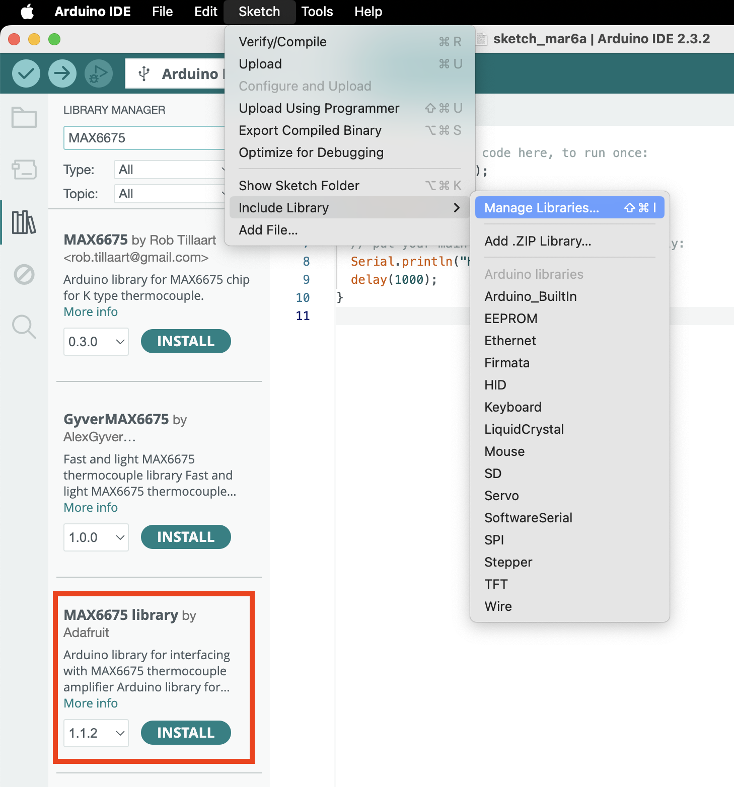
You also need to grab a code library to use the MAX6675 module. Go to Menu -> Sketch -> Include Library -> Manage Libraries (or Shift-Cmd-I or click on the Library icon in the left sidebar) and search for MAX6675.
I used the official library from Adafruit, but you’re of course welcome to experiment with other ones.
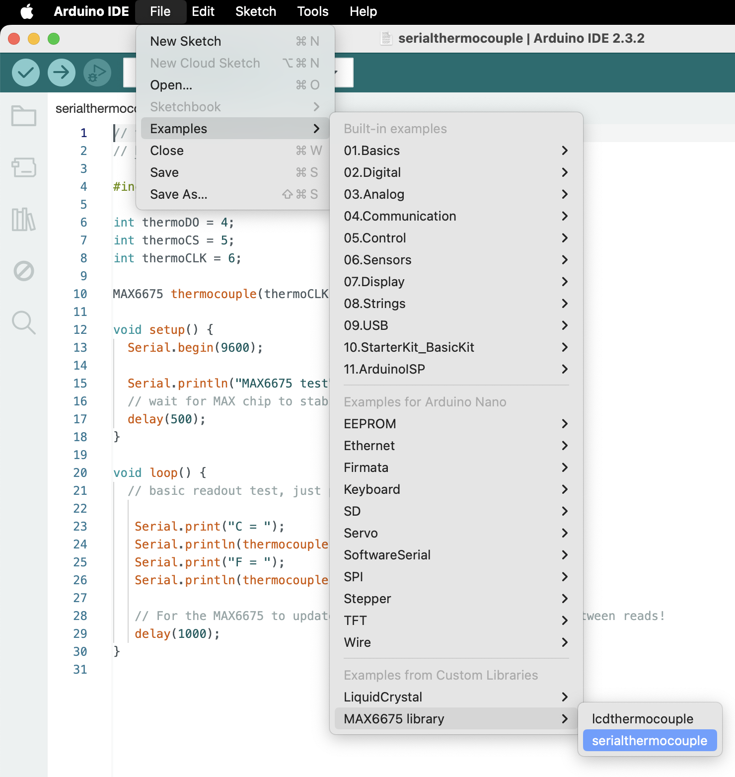
Once the library is installed, open the provided sample code at Menu -> File -> Examples -> MAX6675 library -> serialthermocouple; there’s also a copy of it named MAX6675SerialLogger.ino in this repository.
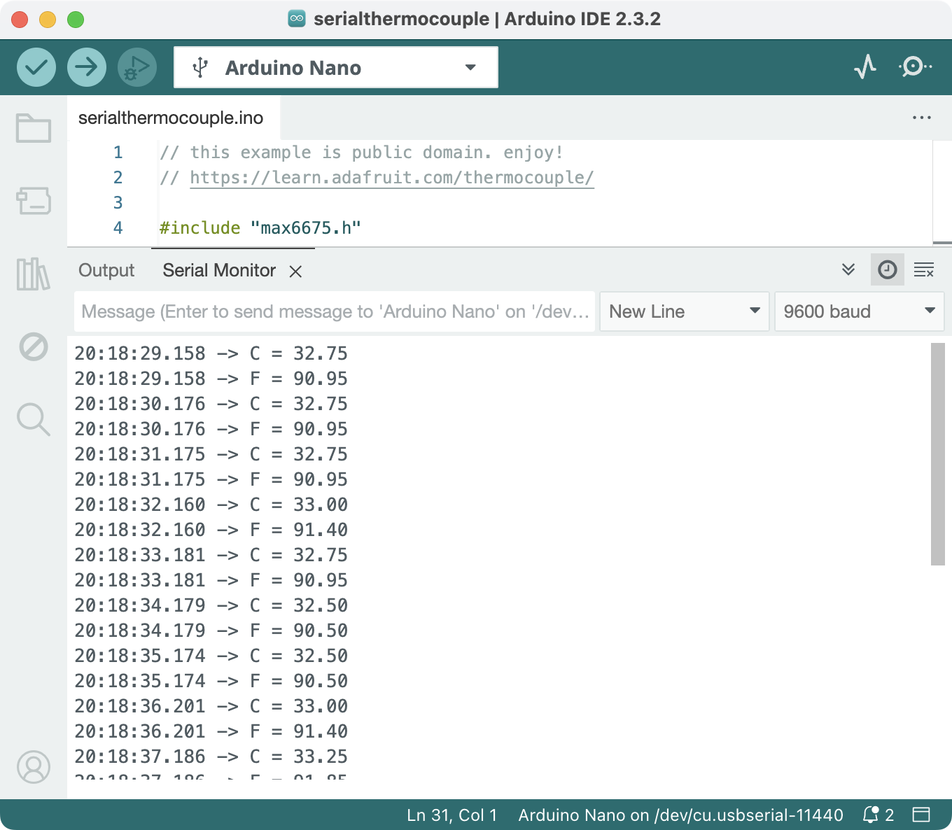
Try uploading their sample script and opening the serial monitor (Menu -> Tools -> Serial Monitor or Shift-Cmd-M or the top right Magnifying glass icon). You should see the thermocouple printing the temperatures onto the Serial Monitor. You could also show their timestamps by toggling the clock icon on the right.
Tips & Tricks
- If you want to use multiple MAX6675 (or MAX31855), you can (should) let them share the same SO and CLK pins and only connect different CS pins to the Arduino.
MAX31855
The MAX31855 is a newer version MAX6675.
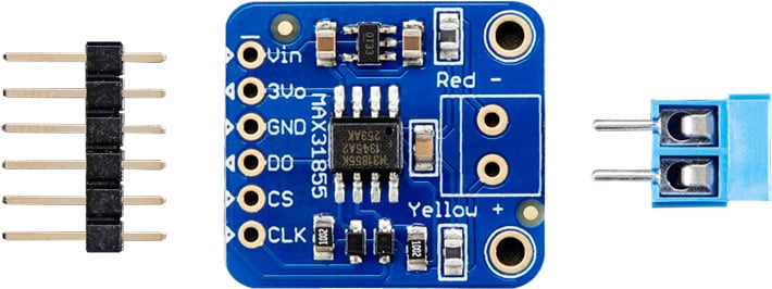
| MAX 31855 | MAX 6675 Equivalent | Arduino to MAX31855 | Sample code (serialthermocouple) variable |
|---|---|---|---|
| Vin (Power input) | VCC | 3.3V or 5V | - |
| V3o (only connect one of V3o or Vin) | - | 3.3V | - |
| GND (Ground) | GND | GND | - |
| SO/DO (Serial Data out) | SO | D3 | MAXDO |
| CS (Chip Select) | CS | D4 | MAXCS |
| CLK (Serial Clock) | SCK | D5 | MAXCLK |
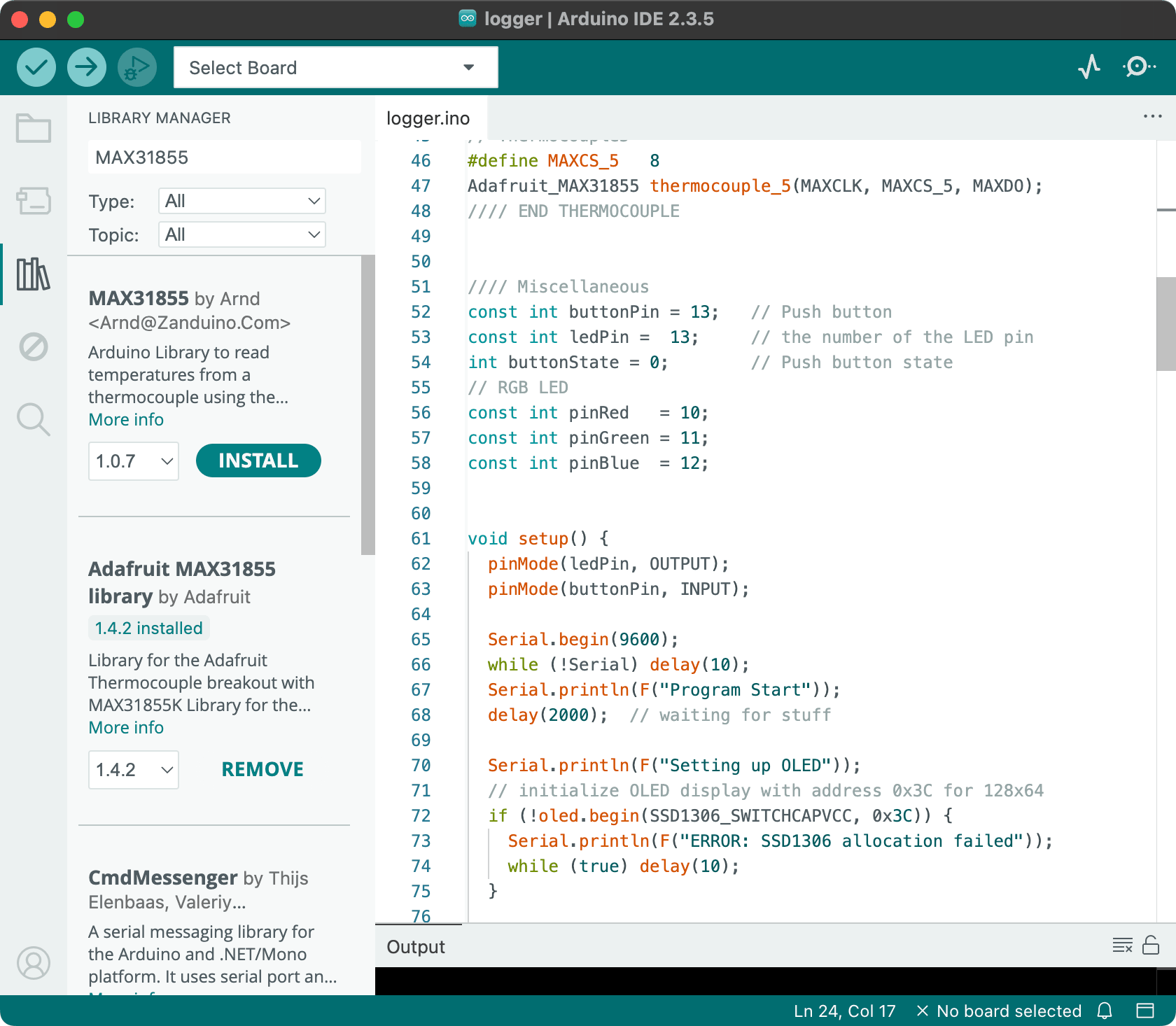
You’ll need to go to Side bar -> Library Manager (or Cmd-Shift-I, or Menu -> Sketch -> Include Library -> Manage Libraries), and search for Max31855 and install the library by Adafruit (feel free to experiment libraries published by others).
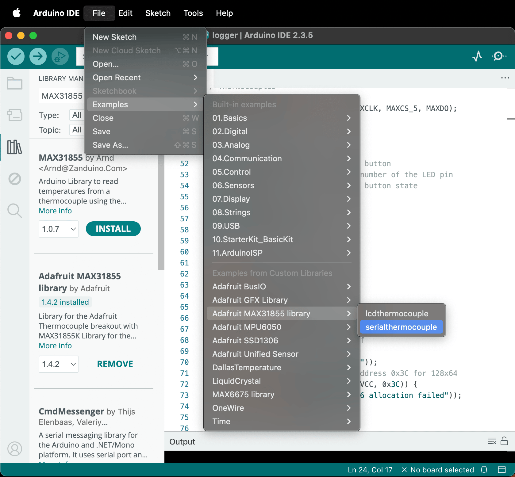
 Once the library is installed, open the provided sample code at
 Menu -> File -> Examples -> Adafruit MAX31855 -> serialthermocouple; there’s also a copy of it named MAX31855SerialLogger.ino in this repository.
 Try uploading their sample script and opening the serial monitor (
Menu -> Tools -> Serial Monitor or Shift-Cmd-M or the top right Magnifying glass icon). You should see the thermocouple printing the temperatures onto the Serial Monitor. You could also show their timestamps by toggling the clock icon on the right.
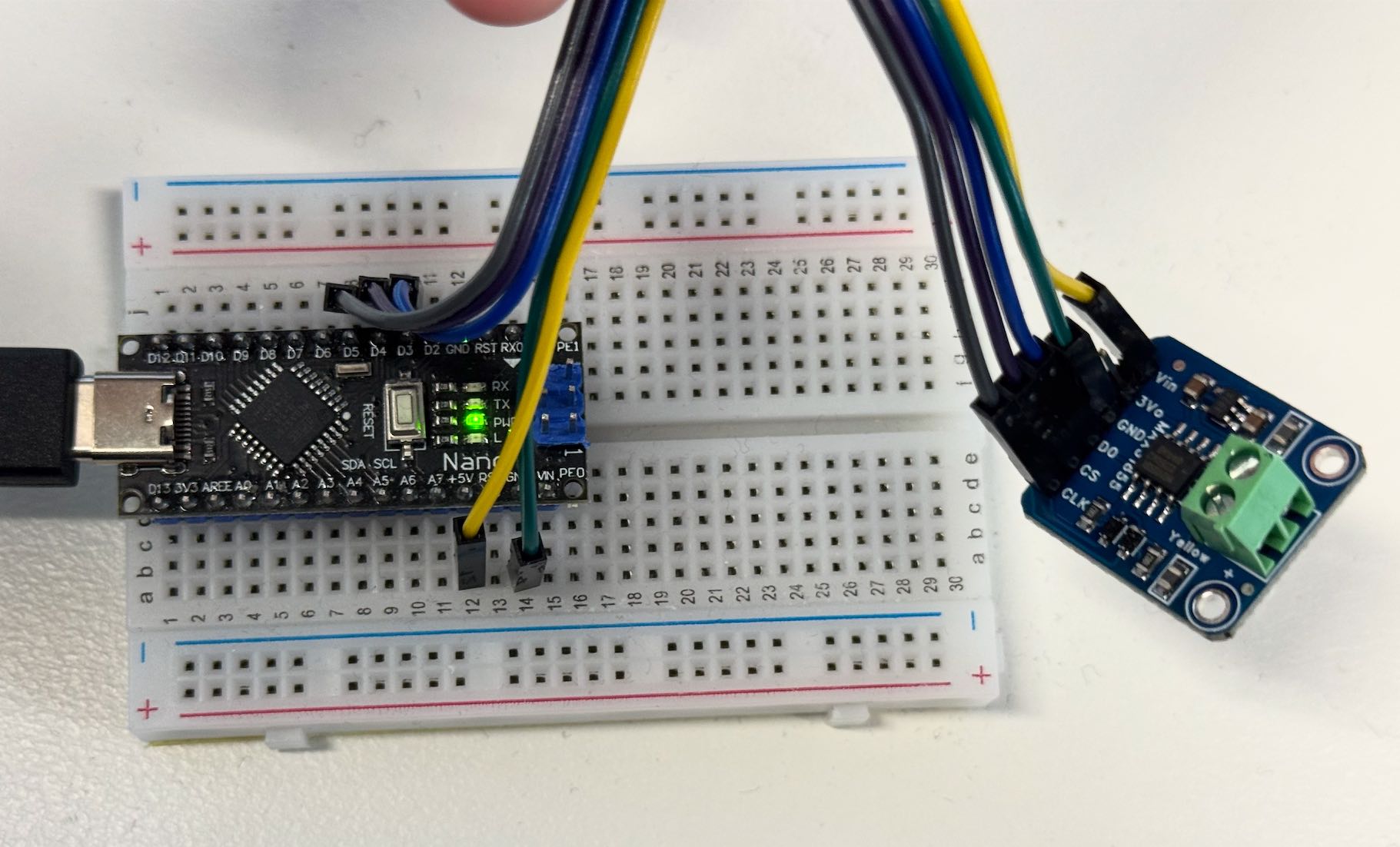
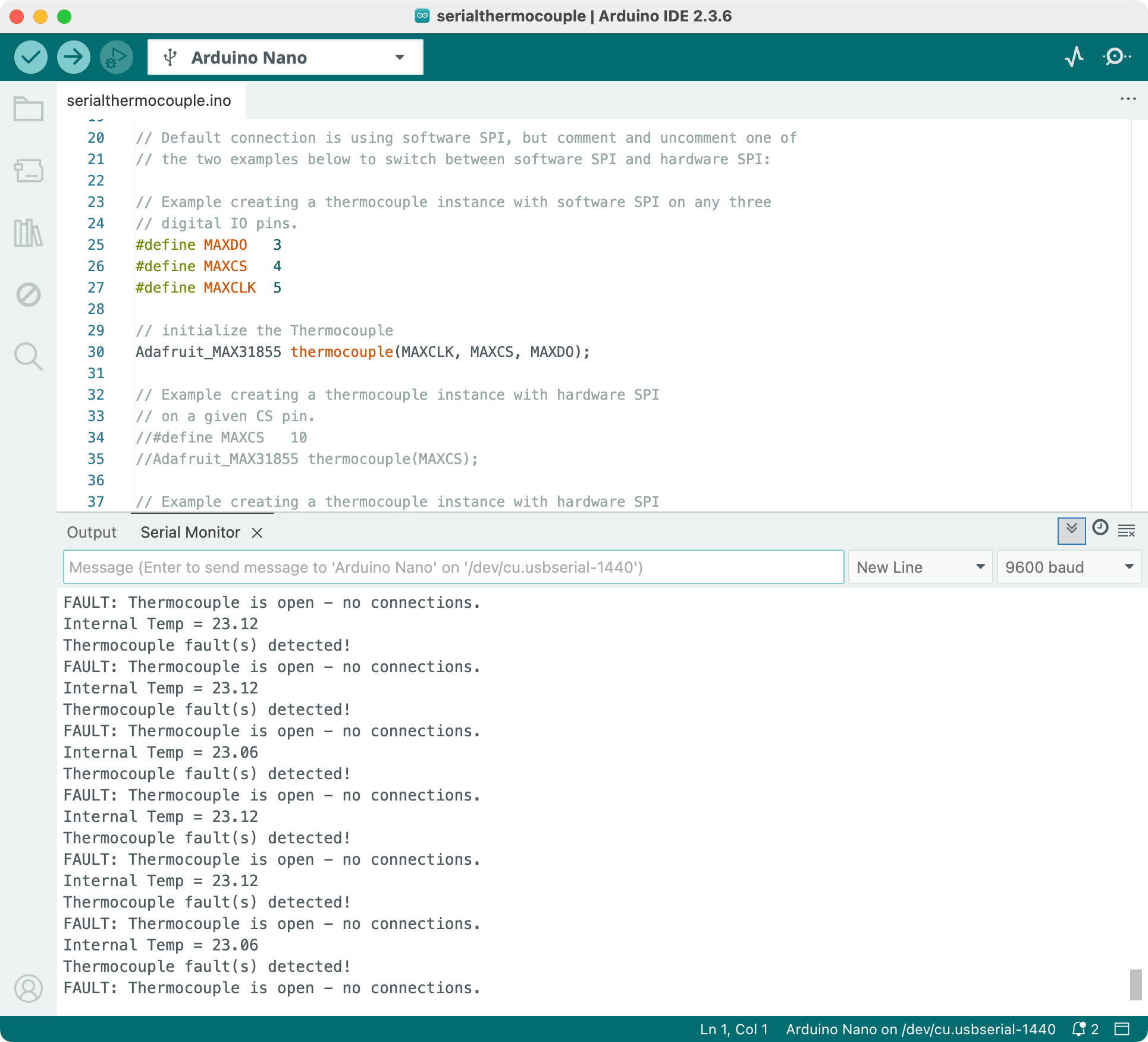 Notice in the above screenshot, I do not have any thermocouple connected to the MAX31855 and its outputting this error message. When there is a thermocouple, it should say something like
 C = 25.00.
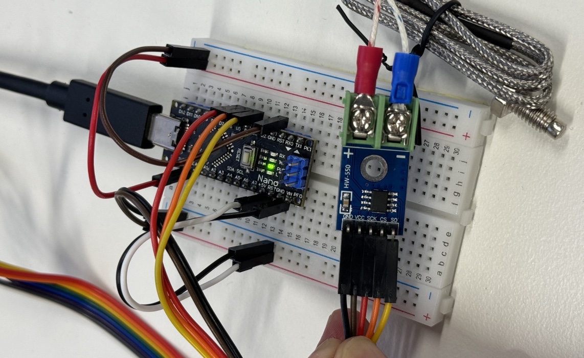
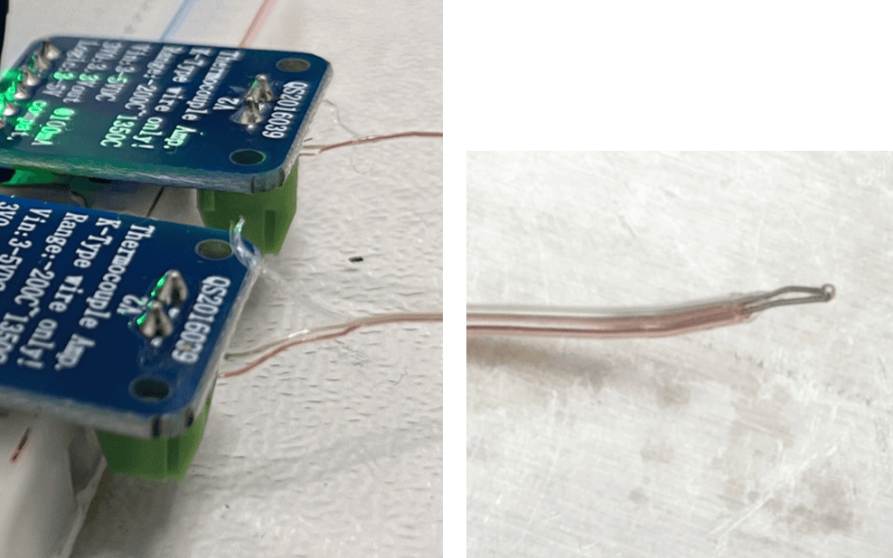 A thermocouple works by generating a voltage difference that corresponds to the temperature difference between the measuring junction (wire soldered end) and a reference point (MAX31855 internal temperature sensor on the PCB).
Depending on the batch, the two thermocouple wires could be as thin as 0.1mm.
To connect it, carefully separate the yellow and red wires and strip their insulation.
Attach the red and yellow wires to the - and + terminals on the MAX31855 respectively.
Tips & Tricks
- If you want to use multiple MAX31855, you should let them share the same
DO(serial data out) andCLK(serial clock) pins physically on the Arduino and give them the sameMAXDOandMAXCLKvariables in the code. - Then, you can connect different
CS(chip select) pins to the Arduino, and assign them to differentMAXCSin the code. This way, you can free up some pins and connect to other sensors or modules. Below photo is an example of five MAX31855s simultaneously.#define MAXDO 2 #define MAXCLK 3 #define MAXCS1 4 Arduino_MAX31855 thermocouple1(MAXCLK, MAXCS1, MAXDO); #define MAXCS2 5 Arduino_MAX31855 thermocouple2(MAXCLK, MAXCS2, MAXDO); ...
DS18B20 Temperature Sensor
For a more detailed guide on using the DS18B20 module, please read https://lastminuteengineers.com/ds18b20-arduino-tutorial/ .
We provide the DS18B20 sensor that comes in the waterproof probe. You also need a 4.7kΩ resistor between VCC and DQ.
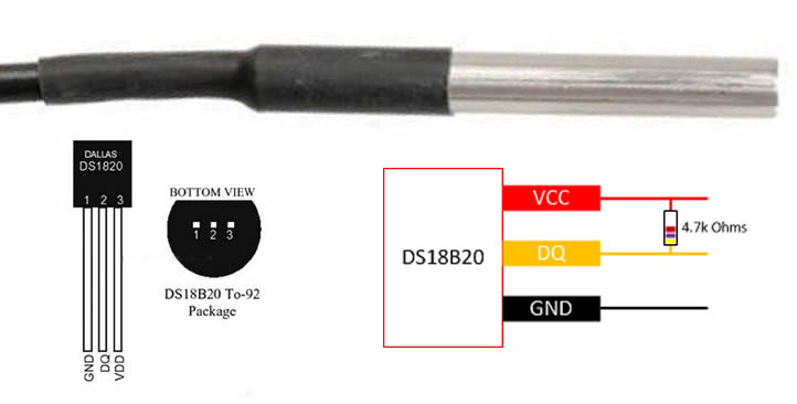
| DS18B20 | Arduino |
|---|---|
| VCC | 3.3V or 5V |
| GND | GND |
| DQ (Data Queue) | D2 |

You also need to grab a code library to use the DS18B20 module. Go to Menu -> Sketch -> Include Library -> Manage Libraries (or Shift-Cmd-I or click on the Library icon in the left sidebar) and search for DS18B20.
I used the official library from DallasTemperature, but you’re of course welcome to experiment with other ones.
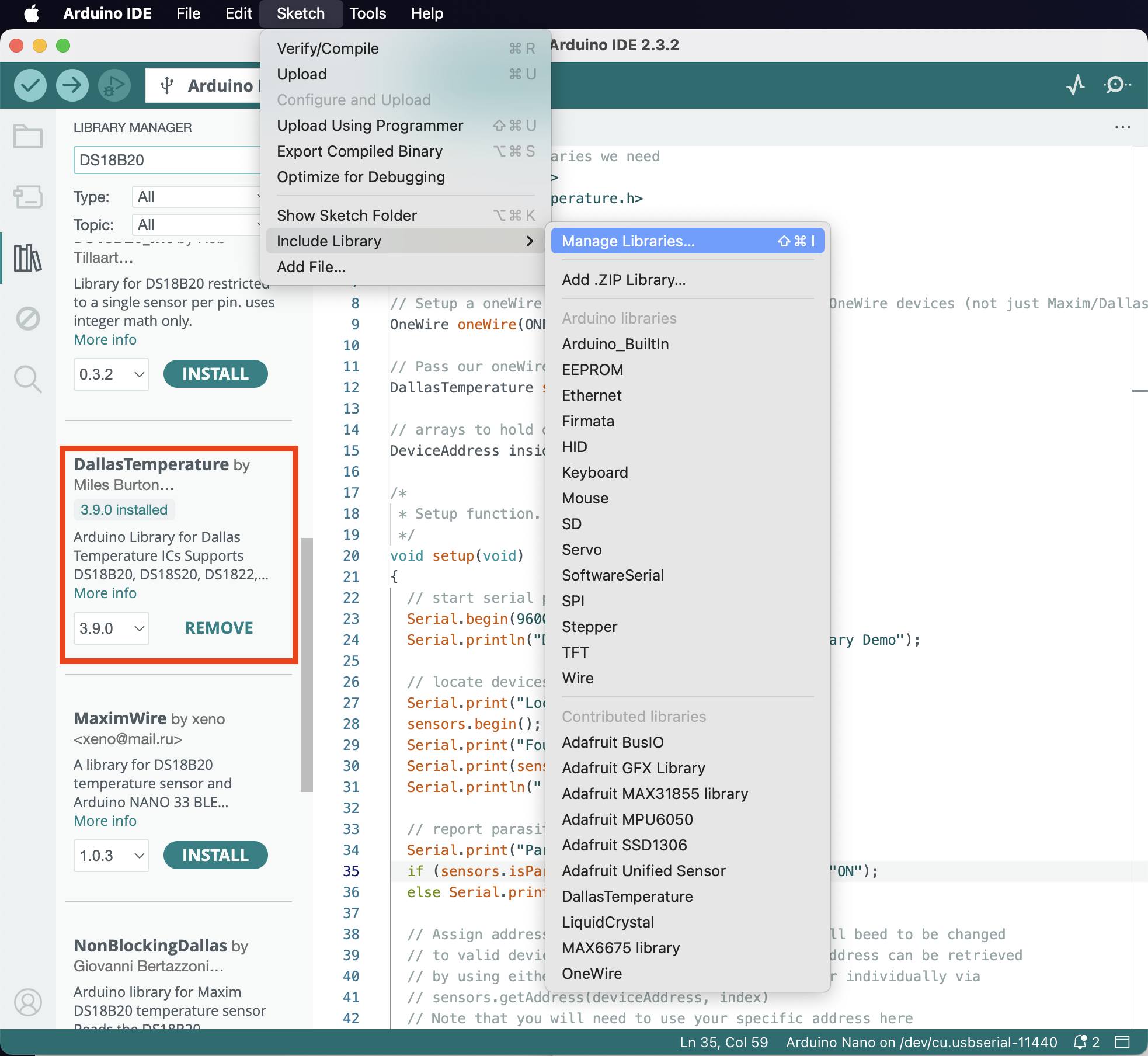
Once the library is installed, open the provided sample code at Menu -> File -> Examples -> DallasTemperatures -> Single; there’s also a copy of it named DS18B20Simple.ino in this repository.
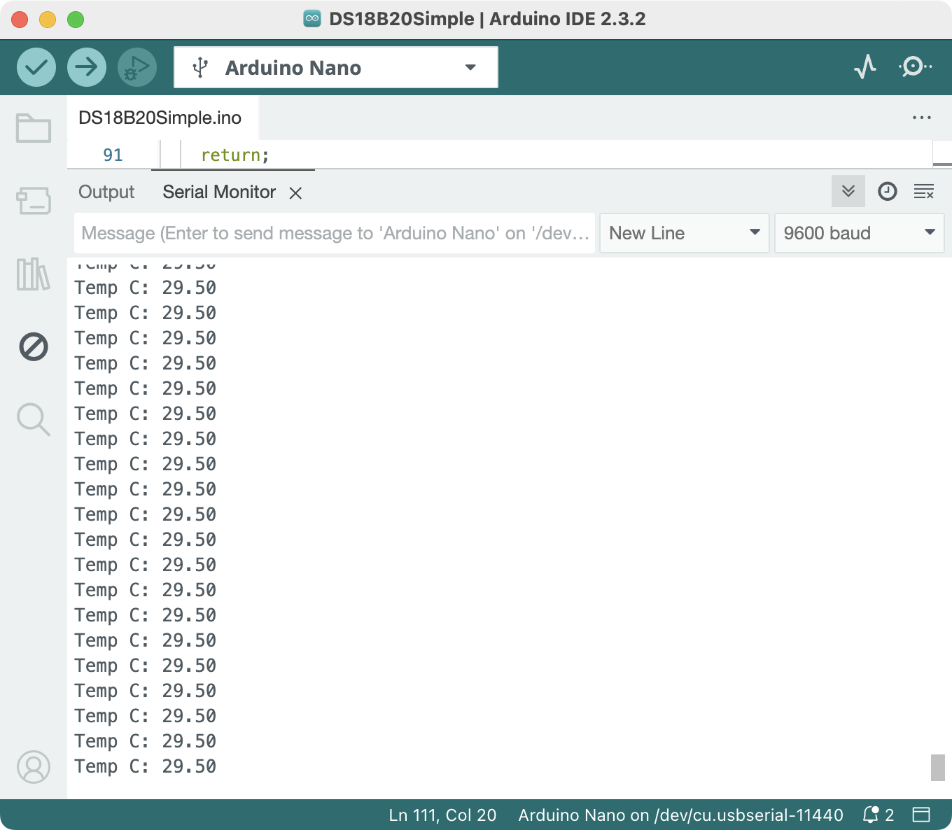
Try uploading their sample script and opening the serial monitor (Menu -> Tools -> Serial Monitor or Shift-Cmd-M or the top right Magnifying glass icon). You should see the thermometer printing the temperatures onto the Serial Monitor. You could also show their timestamps by toggling the clock icon on the right.
DS18B20 usage notes
- Since this sensor only requires a single-pin connection to Arduino, it is straightforward to add multiple sensors; for more info, see
Menu -> File -> Examples -> DallasTemperatures -> TwoPin_DS18B20. - The sensor wires could easily come loose on a breadboard; you should come up with a more permanent solution.
MPU6050 Accelerometer and Gyroscope
For a more detailed guide on using the MPU6050 module, please read https://lastminuteengineers.com/mpu6050-accel-gyro-arduino-tutorial/.
You might need soldering skills to make the pins.
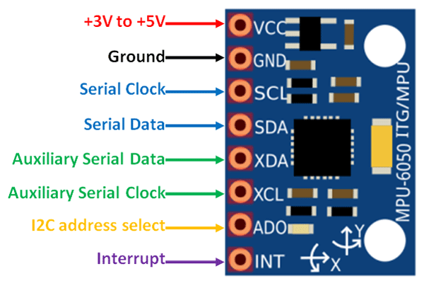
| MPU6050 | Arduino |
|---|---|
| VCC | 3.3V or 5V |
| GND | GND |
| SCL (Serial Clock Line) | A5 (SCL) |
| SDA (Serial Data Line) | A4 (SDA) |
| Other pins not connected. |
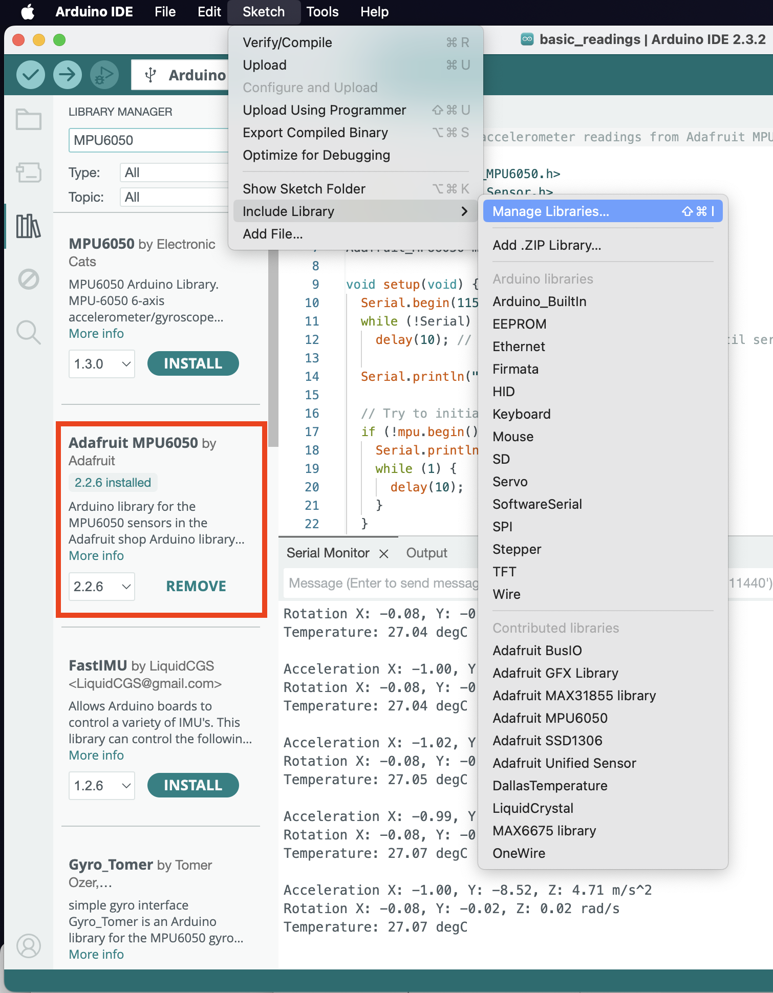
You also need to grab a code library to use the MPU6050 module, go to Menu -> Sketch -> Include Library -> Manage Libraries (or Shift-Cmd-I or click on the Library icon in the left sidebar), and search up MPU6050.
I used the official library of Adafruit, but you’re of course welcome to experiment with other ones.
Once the library is installed, open the provided sample code at Menu -> File -> Examples -> Adafruit MPU6050 -> basic readings; there’s also a copy of it named MPU6050Basic.ino in this repository.
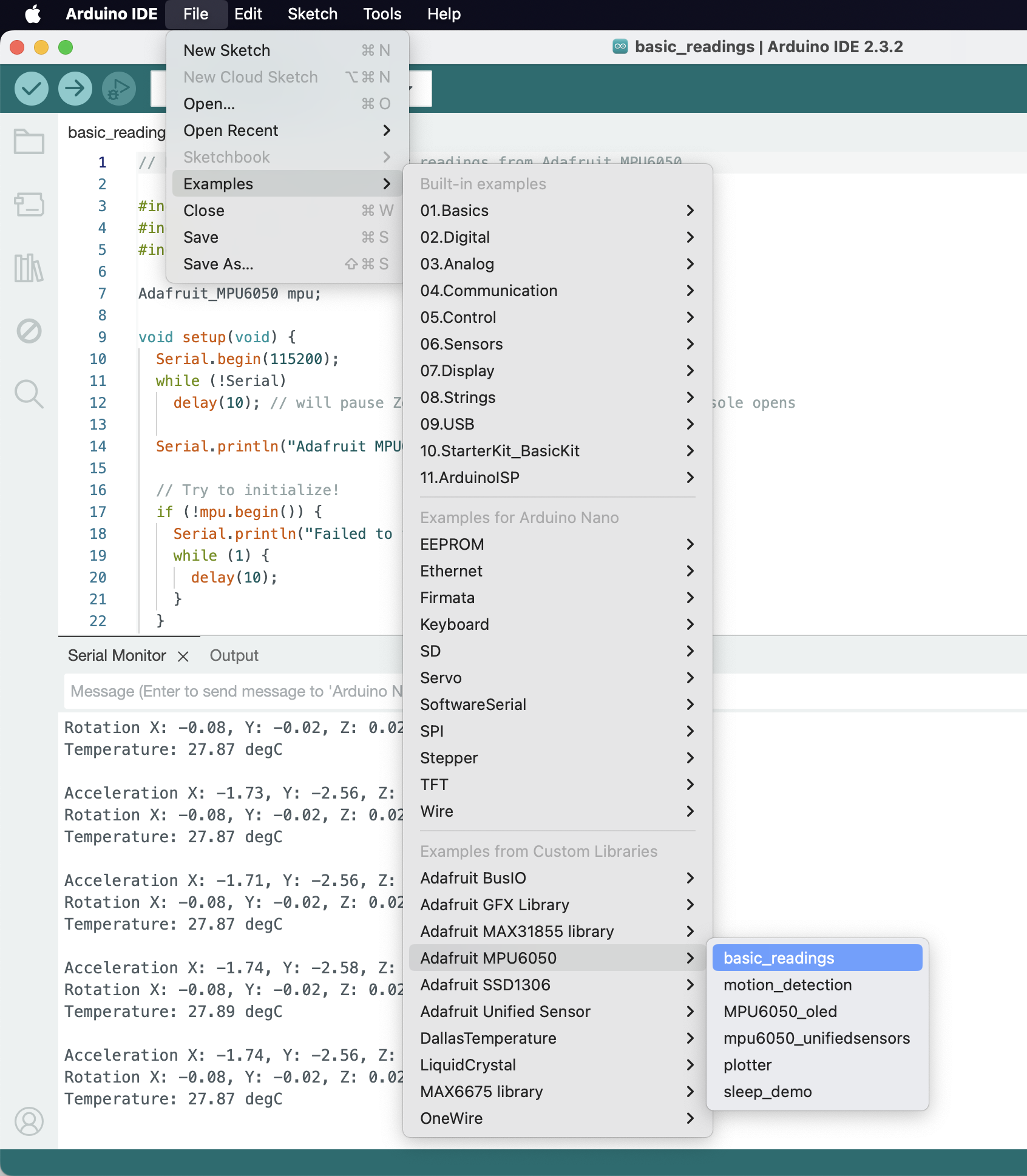
Try uploading their sample script and opening the serial monitor (Menu -> Tools -> Serial Monitor or Shift-Cmd-M or the top right Magnifying glass icon). The sample codes use 115200 serial baud rate (instead of the default 9600), so you need to manually select the baud rate in the serial monitor. Then, you should see it printing the sensors’ values onto the Serial Monitor. You could also show their timestamps by toggling the clock icon on the right.
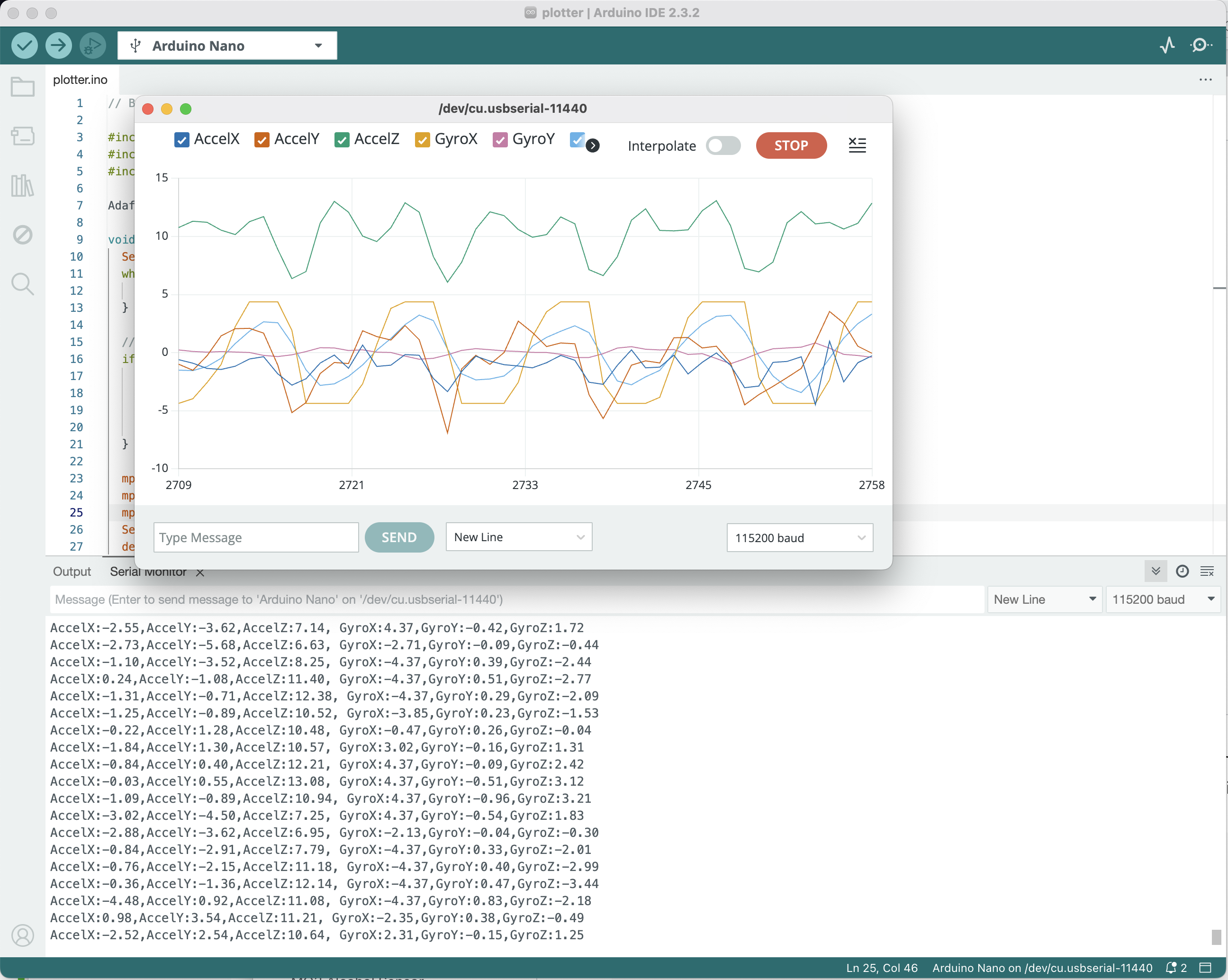
You could also try the script in Menu -> File -> Examples -> Adafruit MPU6050 -> plotter and use the Serial Plotter (top right oscilloscope icon) to get a realtime plot from the accelerometer and gyroscope.
Notes
- MPU6050 has programming sensor range and higher range means lower sensitivity, this is set by
mpu.setAccelerometerRange(MPU6050_RANGE_8_G)andmpu.setGyroRange(MPU6050_RANGE_500_DEG). For example, if you choose maximum acceleration of $2g$, then you maximum sensitivity is $\frac{1}{16384}g \approx 0.6 \mathrm{mm/s^2}$, while max acc set to $16g$ would have sensitivity of $\frac{1}{2048}g\approx 4.8\mathrm{mm/s^2}$. More details about this is available on their datasheet https://invensense.tdk.com/wp-content/uploads/2015/02/MPU-6000-Datasheet1.pdf
ADXL345 Accelerometer
| ADXL345 | Arduino |
|---|---|
| 5V | 5V |
| GND (Power Ground) | GND |
| SCL (Serial Clock Line) | A5 |
| SDA (Serial Data Line) | A4 |
| Other pins not connected. |
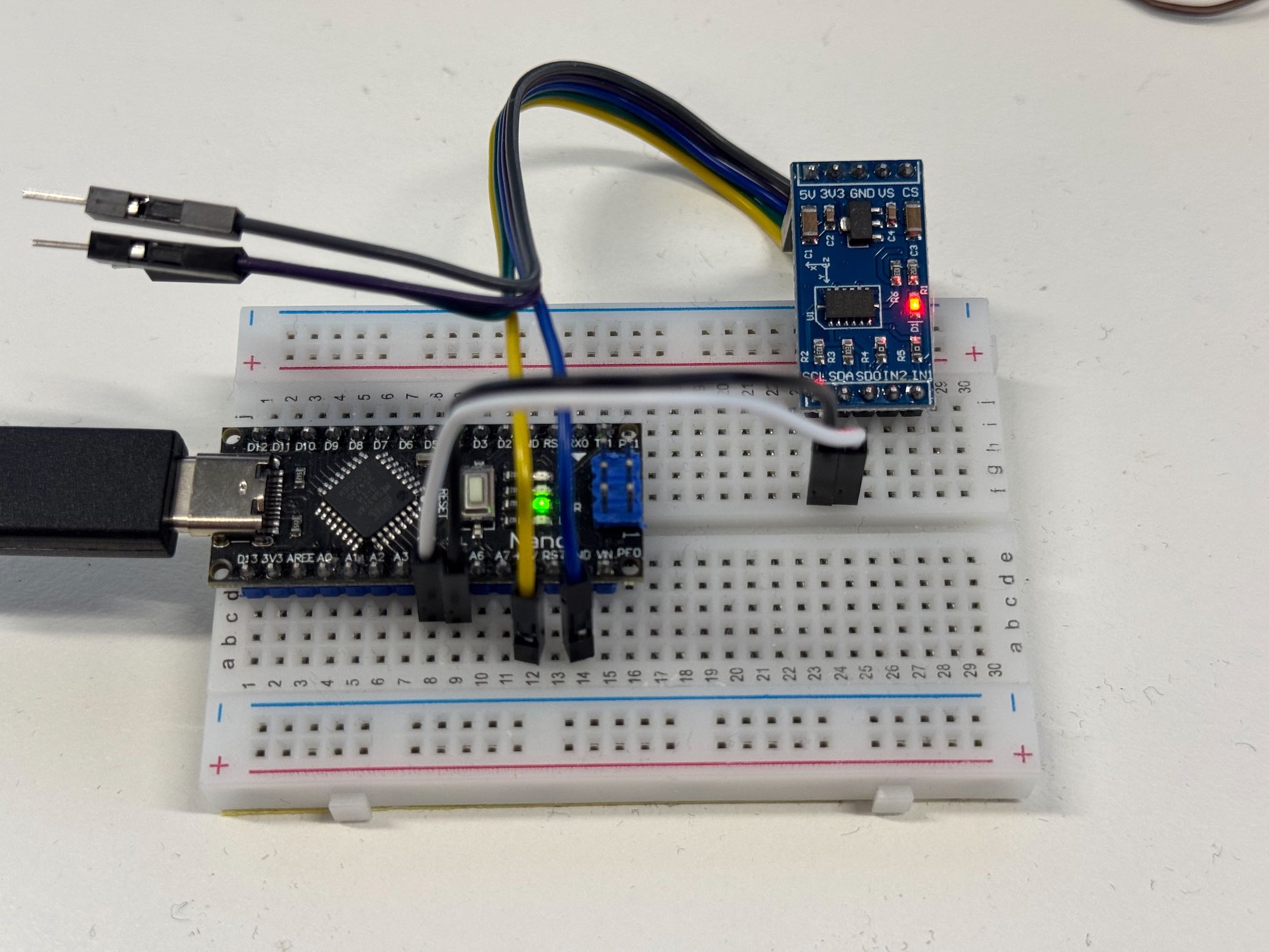
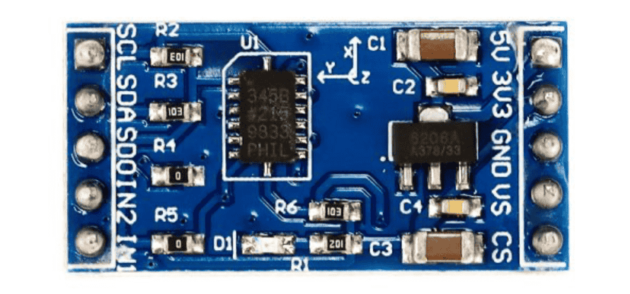
First connect the ADXL345 to the Arduino as shown in the diagram and table above.
Then, you need to grab the Adafruit library for the ADXL345, go to Menu -> Sketch -> Include Library -> Manage Libraries (or Shift-Cmd-I or click on the Library icon in the left sidebar), and search for ADXL345. You’re welcome to explore other libraries.
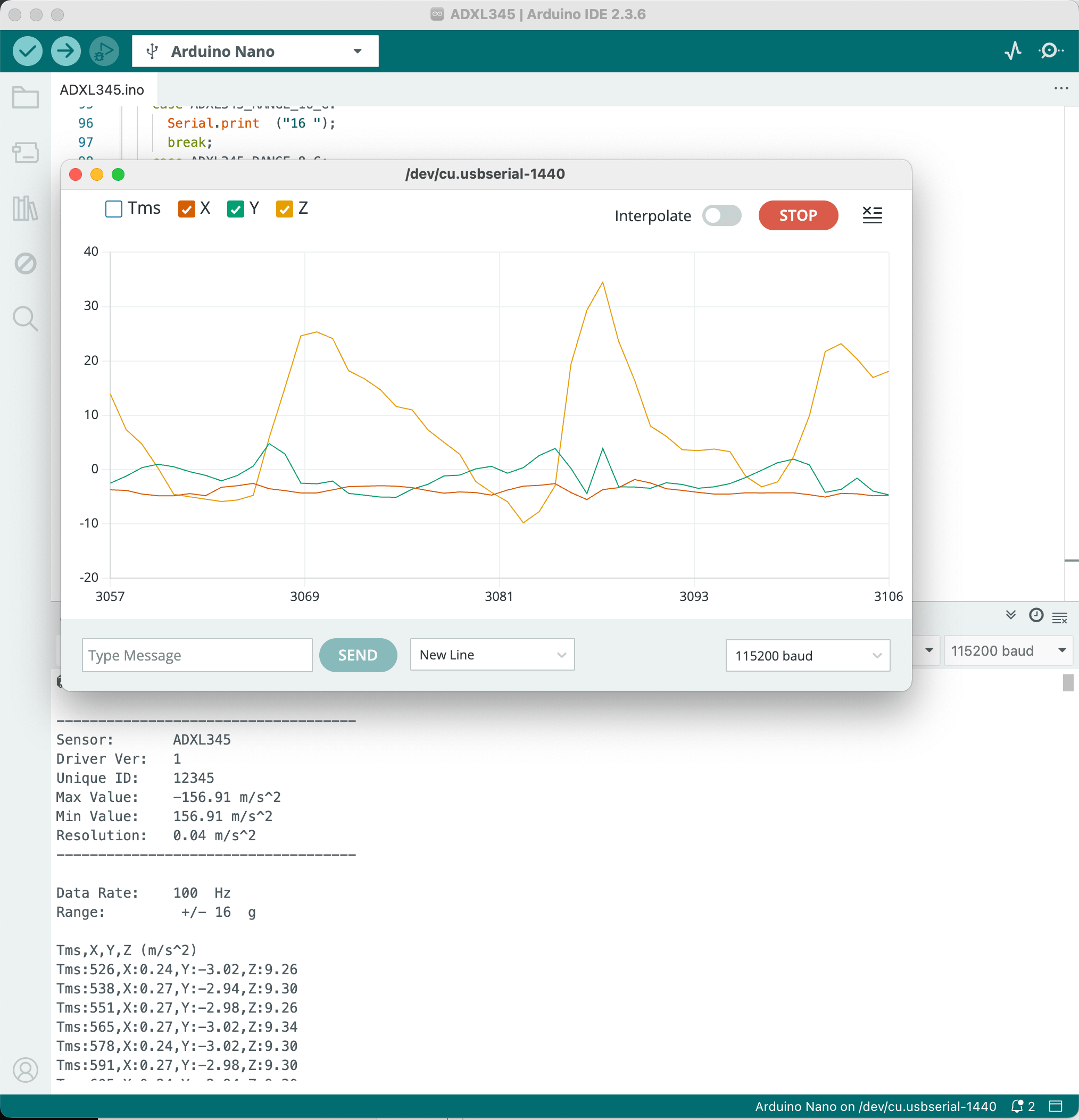
Once it’s installed, you can try their provided sample code at Menu -> File -> Examples -> Adafruit ADXL345 -> sensortest. I’ve also included a slightly modified version in this repository here ADXL345.ino with the correct Serial formatting so you can use it with the Serial Plotter (top right oscilloscope icon). Note you’ll need to change the Serial baud rate to 115200 in the Arduino Serial Monitor.
Notes
- The ADXL345 is a 3-axis accelerometer, if you want rotation data you’ll need to use MPU6050 which is a 3-axis accelerometer plus 3-axis gyroscope.
- The ADXL345 is a 12-bit sensor with configurable range of $2g$, $4g$, $8g$, $16g$, the higher the range, lower the sensitivity. For example the sample code uses 16g range, which has sensitivity of $\frac{16*9.8}{2^{12}} \approx 0.04 \mathrm{m/s^2}$.
Pressure Sensor
Depending on your sensor type, usually, they only need ground and 5V, then the sensor output 0-5V depending on their spec. Then any Arduino’s analog pin can read that 0-5V in 1024 steps using analogRead(pinNo).
- Thus, if for example your pressure sensor range is 0-5PSI, then 0-5Psi will correspond to 0-5V output, and your precision is 0.001 PSI.
- You would need to test your pressure sensors carefully and make sure they are up to spec.
- The pressure sensor in the template data logger (
SDCardDataLogger.ino) is connected to analog pin A1.
Recording Data to SD Card
For a more detailed guide on using the SD card module, please read https://lastminuteengineers.com/arduino-micro-sd-card-module-tutorial/
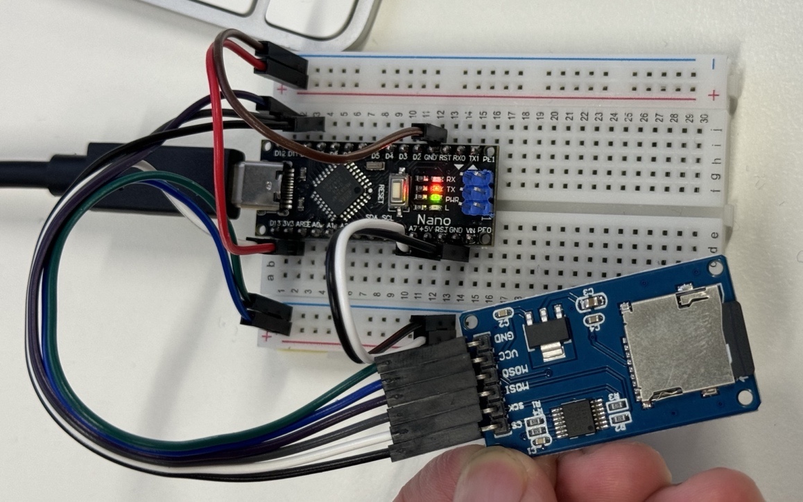
For the SD card module to work with the sample code (SDCardDataLogger.ino), connect the pins as follows,

| microSD Card Module | Arduino |
|---|---|
| VCC | 3.3V or 5V |
| GND | GND |
| MISO (Serial Peripheral Interface Output) | D12 |
| MOSI (Serial Peripheral Interface Input) | D11 |
| SCK (Serial Clock) | D13 |
| CS (Chip Select) | D10 |
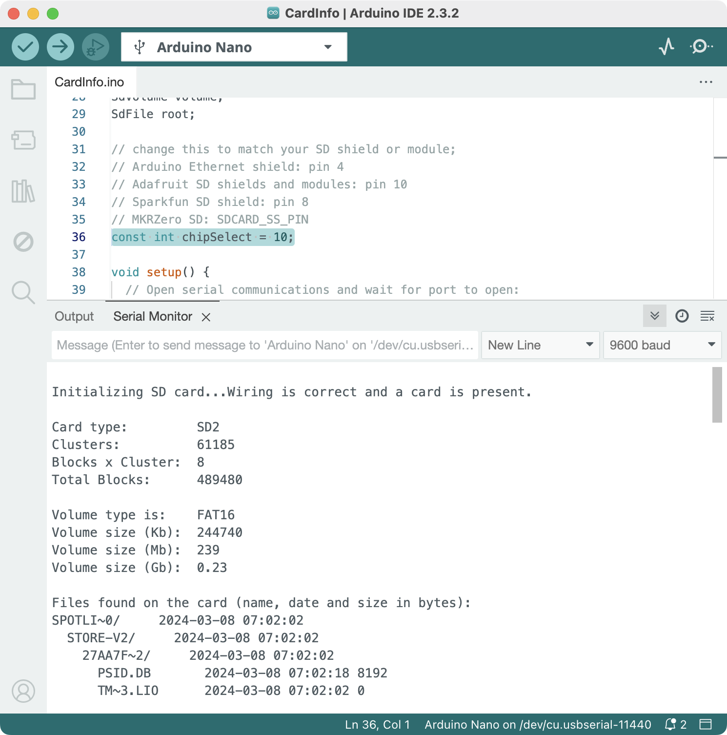
Verify your SD card and reader module works
Open the built-in sample code at Menu -> File -> Examples -> SD -> CardInfo , and change the value of chipSelect at line 36 to 10, then upload the code onto Arduino, you should get the following info from the provided SD card (your’s probably will not show any files, I have some files from macOS filesystem crap).